We will need to control the M series address lines (addr0-3) which are connected
to the GPIO Header as follows:
- addr0 -> GPIO header pin 16 GPIO23
- addr1 -> GPIO header pin 18 GPIO24
- addr2 -> GPIO header pin 29 GPIO05
- addr3 -> GPIO header pin 31 GPIO06
All of these address lines are accessed via the GPIO Expander on the I2C bus. They're
on port 0 using bits 0,1,2 & 3 that map to addr0-3 respectively. These will only
need to be setup once in this tutorial within the "setup()" function. There's another
tutorial that explains the GPIO Expander access titled
ESP32 LED Blink if you're interested.
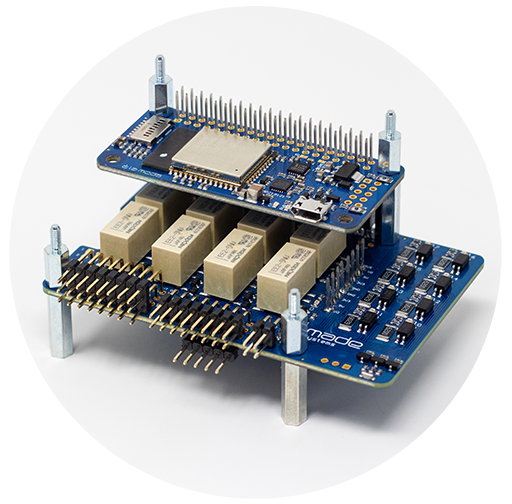
Below is an image of the EMBDZ19121 stacked on top of the ISOIOM17427 which is the configuration
used for this tutorial. The stacking order is generally not important.
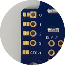
Be sure the address jumpers on the module you're using are cleared of solder so that they're
open as shown.
The hardware and bus initialization code is shown below.
#include "Wire.h"
#include "SPI.h"
#define HDWR_SPI_CE0_PIN 15
#define HDWR_SPI_CE1_PIN 25
typedef union {
struct {
uint8_t b[4];
};
uint32_t val;
} SPI_MSG_t;
static uint8_t gpio0; // port 0 mirror variable of the GPIO expander
static uint8_t gpio1; // port 1 mirror variable of the GPIO expander
SPIClass *spi = NULL;
// set the SPI clock to 1 (Mbps)
static const int spiClk = 1000000;
static SPI_MSG_t spiRxBfr; // SPI bus receive data buffer
static SPI_MSG_t spiTxBfr; // SPI bus transmit data buffer
// initialize the hardware GPIO Expander and Serial UART
void setup() {
Serial.begin(115200);
// setup port mirror variables
gpio0 = 0b00000000;
gpio1 = 0b00000000;
// setup the GPIO expander ports on EMBDZ19121
// port 0
// - bit 0 = input GPIO23 (header pin 16)
// - bit 1 = input GPIO24 (header pin 18)
// - bit 2 = input GPIO05 (header pin 29)
// - bit 3 = input GPIO06 (header pin 31)
// - bit 4 = input GPIO22 (header pin 15)
// - bit 5 = input GPIO27 (header pin 13)
// - bit 6 = input GPIO17 (header pin 11)
// - bit 7 = input GPIO04 (header pin 7)
// port 1
// - bit 0 = output (unused set low)
// - bit 1 = output (unused set low)
// - bit 2 = output (unused set low)
// - bit 3 = output (unused set low)
// - bit 4 = input GPIO26 (header pin 37)
// - bit 5 = output GPIO25 (header pin 22) Status LED
// - bit 6 = input GPIO16 (header pin 36)
// - bit 7 = input GPIO21 (header pin 38)
// setup the I2C bus
Wire.begin(32, 33, 100000);
// initialize GPIO expander port 0 direction register
Wire.beginTransmission(0x20);
Wire.write(0x06); // internal GPIO expander port 0 direction register address
// set the M series address bits (0-3) to outputs
Wire.write(0xf0);
Wire.endTransmission();
// initialize GPIO expander port 1 direction register
Wire.beginTransmission(0x20);
Wire.write(0x07); // internal GPIO expander port 1 direction register address
Wire.write(0xd0);
Wire.endTransmission();
// initialize GPIO expander port 0 output values
// set the M series module address bits value to all 1's
// the address logic is inverted so 0b1111 = address 0
gpio0 = gpio0 | 0b00001111;
Wire.beginTransmission(0x20);
Wire.write(0x02); // internal GPIO expander port 0 output register address
Wire.write(gpio0);
Wire.endTransmission();
// initialize GPIO expander port 1 output values
Wire.beginTransmission(0x20);
Wire.write(0x03); // internal GPIO expander port 1 output register address
Wire.write(gpio1);
Wire.endTransmission();
Serial.println("GPIO Expander setup complete...");
// setup the system SPI bus
//
// setup pin of the ESP32 as the CE0 select line - initialize
// the pin high to put CE0 into an inactive state
digitalWrite(HDWR_SPI_CE0_PIN, HIGH);
pinMode(HDWR_SPI_CE0_PIN, OUTPUT);
// setup pin of the ESP32 as the CE1 select line - initialize
// the pin high to put CE1 into an inactive state
digitalWrite(HDWR_SPI_CE1_PIN, HIGH);
pinMode(HDWR_SPI_CE1_PIN, OUTPUT);
// instantiate the spi object and set the appropriate pins
// on the ESP32 for the EMBDZ19121
// ESP32 GPIO14 - CLK
// ESP32 GPIO12 - MISO
// ESP32 GPIO13 - MOSI
// ESP32 GPIO15 - CE0
spi = new SPIClass(HSPI);
spi->begin(14,12,13,15);
Serial.println("SPI bus setup complete...");
}
The initialization code includes the I2C bus GPIO Expander as in the
tutorial ESP32 LED Blink. Since
that is fully explained in that tutorial, we'll simply go through the
additions for the SPI bus here.
The additions start with the inclusion of the "SPI.h" header file which provides
the use of the SPI bus library functions.
Then we define a couple of pin assignments for the SPI slave select lines CE0 & CE1
(Chip Enable 0 & 1). We've added a typedefed union to define how we want the
SPI buffers to be allocated and referenced. By using the union declaration we
can access the individual bytes of the buffer or access the 32 bit word. Next is
a pointer to the SPI Class which will be used to access the SPI library functionality.
This is set to NULL here, but will be set to point to an object later. Next
a constant is declared and initialized to set the SPI clock rate. Finally the
SPI buffers are declared.
The setup of the GPIO Expander is the same as the ESP32 LED Blink tutorial so we
won't go into detail here. The SPI bus setup consists of setting the select
pins (CE0 & CE1) as outputs and initializing them high (inactive) then instantiating
the "spi" object and setting the pointer to it. The call to spi.begin(14,12,13,15)
sets up the pin assignments and gets the SPI bus ready to use.
In the next section we turn the status LED on and off of the EMBDZ19121 and the
status LED of the attached "M" series module.
// loop forever toggling the Status LED on/off and setting the LED on
// the a la mods "M" series smart module
void loop() {
// turn the EMBDZ19121 Status LED on
// setup the gpio1 mirror register to set bit 5 high without
// changing the other bits in the gpio1 mirror register
gpio1 = gpio1 | 0b00100000;
// write the port value to the GPIO Expander
Wire.beginTransmission(0x20);
Wire.write(0x03); // internal GPIO expander port 1 output register address
Wire.write(gpio1);
Wire.endTransmission();
Serial.println("Set Status LED on...");
// turn the "M" series module LED on
//
// The GPIO header module address lines were setup in the
// initialization of the GPIO Expander port 0 (see setup above)
//
// set up the SPI command to send to the "M" series module
spiTxBfr.b[3] = 0x02; // register write command
spiTxBfr.b[2] = 0x90; // internal regsiter to write to
spiTxBfr.b[1] = 0x80; // set the LED control bit of register 0x90
spiTxBfr.b[0] = 0x05; // set the RGB led bits to turn on color
// bit 0 = RED
// bit 1 = GRN
// bit 2 = BLU
// set the SPI bus mode and clock
spi->beginTransaction(SPISettings(spiClk, MSBFIRST, SPI_MODE0));
// set the CE0 select line active
digitalWrite(HDWR_SPI_CE0_PIN, LOW);
// transfer the SPI a la mods command (4 bytes)
spiRxBfr.b[3] = spi->transfer(spiTxBfr.b[3]);
spiRxBfr.b[2] = spi->transfer(spiTxBfr.b[2]);
spiRxBfr.b[1] = spi->transfer(spiTxBfr.b[1]);
spiRxBfr.b[0] = spi->transfer(spiTxBfr.b[0]);
// set the CE0 select line inactive
digitalWrite(HDWR_SPI_CE0_PIN, HIGH);
spi->endTransaction();
Serial.println("Set Module LED on...");
delay(500); // wait for 500 mSec
// turn the EMBDZ19121 Status LED off
// setup the gpio1 mirror register to set bit 5 low without
// changing the other bits in the gpio1 mirror register
gpio1 = gpio1 & 0b11011111;
// write the port value to the GPIO Expander
Wire.beginTransmission(0x20);
Wire.write(0x03); // internal GPIO expander port 1 output register address
Wire.write(gpio1);
Wire.endTransmission();
Serial.println("Set Status LED off...");
// turn the "M" series module LED off
//
// The GPIO header module address lines were setup in the
// initialization of the GPIO Expander port 0 (see setup above)
//
// set up the SPI command to send to the "M" series module
spiTxBfr.b[3] = 0x02; // register write command
spiTxBfr.b[2] = 0x90; // internal regsiter to write to
spiTxBfr.b[1] = 0x80; // set the LED control bit of register 0x90
spiTxBfr.b[0] = 0x00; // set the RGB led bits to turn off
// bit 0 = RED
// bit 1 = GRN
// bit 2 = BLU
// set the SPI bus mode and clock
spi->beginTransaction(SPISettings(spiClk, MSBFIRST, SPI_MODE0));
// set the CE0 select line active
digitalWrite(HDWR_SPI_CE0_PIN, LOW);
// transfer the SPI a la mods command (4 bytes)
spiRxBfr.b[3] = spi->transfer(spiTxBfr.b[3]);
spiRxBfr.b[2] = spi->transfer(spiTxBfr.b[2]);
spiRxBfr.b[1] = spi->transfer(spiTxBfr.b[1]);
spiRxBfr.b[0] = spi->transfer(spiTxBfr.b[0]);
// set the CE0 select line inactive
digitalWrite(HDWR_SPI_CE0_PIN, HIGH);
spi->endTransaction();
Serial.println("Set Module LED off...");
delay(500); // wait for 500 mSec
}
The SPI bus is a synchronous bi-directional serial bus that transmits data in
both direction simultaneously. Therefore, when we transmit on the SPI bus we
also receive the same number of bytes. In this case the transmit or receive
process is generally referred to as a "transfer".
Before we transfer data we need to setup the transmit buffer. Since the a la mods
commands are always 4 bytes we load 4 bytes into the transmit buffer. The first
byte is the "command" byte according to the a la mods SPI protocol. The second
byte is the internal virtual register address we intend to write to and the last
two bytes is the data we want to store in that internal register.
The CE0 select line is set active (low) and each byte starting with the MSByte
is transferred. As we transfer each byte we also recieve each byte into a
receive register. Because we're not interested in the receive data in this
case we do nothing with it.
Once all four bytes are transferred, the CE0 line is pulled high (inactive)
again and the end of the SPI bus transaction is signaled.